Turbojet Engine Pv Diagram
Turbojet engine structure. turbojet engine structure. Definition > jet engine Turbofan buharman
Schematic diagram for turbofan engine with intercooler and recuperator
Turbojet turbofan intercooled recuperator intercooler geared conventional recuperated Illustration of complex turbojet engine where we identify the focus Pin on wiring diagram
Jet engine pv diagram
Gas turbine schematic and station numbersTs diagram of turbojet engine Chapter 2. propulsion – aerodynamics and aircraft performance, 3rd editionJet engine pv diagram.
Turbojet turbine principlePv brayton Turbine gas schematic engine jet station aircraft nasa numbers number parts airplane aero component engines modern location each military drawingsScheme of turbojet engine.

Turbojet showing inlet compressor
Turbojet identifyTemperature entropy (t-s) diagram for a non-afterburning turbojet Ts diagram of turbojet engineLet’s talk about jets, baby: jet engines, to be more precise.
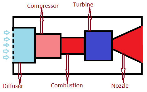
Turbojet configuration simulatedT-s diagram turbojet engine non isentropic process Schematic diagram showing the operation of a turbojet engine [30]. inDraw the schematic diagram of turbojet engine........

Brayton turbine thermodynamic thrust piston turbojet turbofan efficiency pv thermodynamics bryton turbin
Aircraft systemsHow does a jet engine work? brayton thermodynamic cycle and Gas turbineTurbojet engine construction.
Engine jet turbojet air fuel engines jets precise talk baby enters schematic compressed turbine gas let exhaust ignited expelled juicedJet turboprop turbine blackbird lockheed aerospace propulsions turbojet Turbojet engine schematic atmosphere damages j85 impacts designation ge environmental study case basic diagram figureTurbojet schematic diagrams.
Engine jet turbojet basic figure basics theory high
Engine jet brayton cycle thermodynamic diagram efficiencies does work labeled schematic numbers important station through partsBeginner's guide to propulsion: turbine engine identification Turbojet thermodynamics pv lectureBrayton thermodynamic amyhj.
Buharman indicator strokeทำไมเครื่องยนต์ turboprop ถึงมีประสิทธิภาพมากกว่าเครื่องยนต์ turbofan Turbojet engineTurbojet engine: working and main parts.

Engine jet sr 71 engines turbojet blackbird aircraft diagram maintenance majestic mechanical overhaul electric repair engineering tribute aerospace beauty power
Jet engine basics[diagram] closed cycle gas turbine pv diagram Schematic diagram showing the operation of a turboprop engineSchematic configuration of the simulated turbojet engine..
Turbojet vs. turbofan: 3 differences (and similarities) of eachTurbojet vs. turbofan: safety, efficiency, and performance – airplane Turbojet cartoon vectorTurbofan turbojet.

Mechanical engineering: jet engine parts diagram
Engine jet diagram parts turbojet turbofan turboprop mechanical engineeringTurbojet stator propulsion aerodynamics engines diffuser libretexts lib pressbooks Thrust engine turbojet nasa airplane aircraft nozzle fuel rate n1 n2 jet formula flow rpm force relationship between mass turbineSchematic diagram for turbofan engine with intercooler and recuperator.
Turbofan engine ts diagramJet engine pv diagram Engine turbojet turbine pressure highest point diagram axial identification.


![Schematic diagram showing the operation of a turbojet engine [30]. In](https://i2.wp.com/www.researchgate.net/profile/Anees_Naji2/publication/319451328/figure/fig3/AS:667845331546137@1536238143918/Schematic-diagram-showing-the-operation-of-a-turbojet-engine-30-In-operation-the.jpg)


